Re-Tightening of Screws
All nuts and bolts should be re-tightened after the first 20 hours of service. This also applies to machines which have undergone repair work.
Taper Lock Bushes
Check all taper lock bushes on the machine after the first 20 hours or after repair work to ensure they are secure.
Tap with a hammer and blunt punch in a circular motion around the taper lock then pinch up the socket head screws with a socket wrench, Fig 5.1.
If taper lock bushes are to be replaced the following instructions should be followed:-
- Clean the taper lock bush to completely remove all traces of the protective film.
- Clean thoroughly the pulley and shaft end onto which the bush is to be fitted to remove oil and dirt.
- Push the bush into the pulley hub and rotate until the holes are in alignment.
- Apply loctite solution (or similar) to the threads of the screws before inserting into the assembly - Do not tighten!
- Fit the pulley / taper lock assembly onto the shaft and slide into the correct position.
Note: It will also be necessary to loosely fit the drive belt over the pulley at this stage.
Remember when positioning the assembly on the shaft that when the bolts are tightened the bush will nip the shaft first before drawing the pulley onto the bush.
- Tighten the screws gradually a few turns of each at a time until all bolts are locked up very tightly, Fig 5.1. Note: Use a piece of pipe or wrench to increase leverage.
- Tap the face of the bush using a hammer and blunt punch to ensure correct seating on the shaft and further tighten screws.
Repeat this procedure once or twice more tapping around the face of the bush and tighten up the screws.
- Check the tightness of the screws once the drive has run under load for a short time.
- Fill empty holes in the bush with grease to exclude dirt.
Note: Torque values are given in the table above.
Tightening of Hydraulic Fittings
Over tightening of hydraulic fittings can cause oil leaks. This can be avoided by correct tightening of fittings.
When assembling / re-assembling pipework on the machine always finger tighten the fitting to the point of resistance, then using a suitable spanner tighten by a further 60°.
Following these instructions will ensure correct contact with captive seal within fitting blocking any possible leakage path.
Filter
The separator’s hydraulic system is protected by a filter connected to the main feed line, Fig 5.2.1, which is used to strain impurities from the oil before it reaches the hydraulic valves.
Important: The filter must be replaced each season.
Failure to replace the filter as recommended could result in unfiltered oil entering the system and causing problems with the hydraulic services and damage to the spool valves.
The filter body has an electrical clogging sensor, Fig 5.2.2, which sends a signal to the control box in the event of a blocked filter. When the blocked filter symbol is displayed on the control panel screen the filter should be replaced as soon as possible.
Drive Belt Tension
Drive system belt tensions are checked before the machine leaves the factory. If however a belt is removed for maintenance it should be re-installed to fit comfortably
- neither too tight or too loose.
Screw type adjusters are fitted to allow belt tensions to be fine tuned and checks can be made to ensure the correct level of tension is achieved.
Attach a spring balance to the belt at mid span, Fig 5.3 (a), and check the force necessary to deflect the belt by 1/100th of its span centres (b). The force measured should equal that shown in the table opposite. If not, adjust the tensioner screws accordingly.
A tension meter can also be used to read the level of tension and frequency readings are also given opposite.
Gearbox
The Web drive gearbox is fitted with a level plug for inspection and top up, Fig 5.5.1.
Check level regularly and top up if required with EP 90 gear oil. The gearbox holds 1½ litres of oil.
Clutches
Two 5 row clutches are fitted to the output shafts on either side of the web drive gearbox, Fig 5.8.
A further clutch is fitted to the central rear star shaft. These clutches do not require adjustment!
If clutch slip occurs - Disable the machine by switching off the tractor engine and removing the ignition key.
Check over the machine for a blockage or for jamming of a mechanical component such as a trapped stone and clear as necessary.
If the clutch continues to slip for no apparent reason such as jamming or soil overloading - the clutch pawls and springs may be worn or damaged.
**Warning** - Clutch refurbishment requires special tools! Consult your ScanStone dealer.
Each clutch has a grease nipple - Check lubrication schedule for greasing intervals.
Wheels and Tyres
Check tyres periodically to ensure the correct pressure is maintained - See decal to the right.
Keep tyres away from sharp objects and from petrol, grease, oil and solvents.
Check wheel stud torque settings at 8 hour intervals and tighten if required to 271 N/m. See decal below.
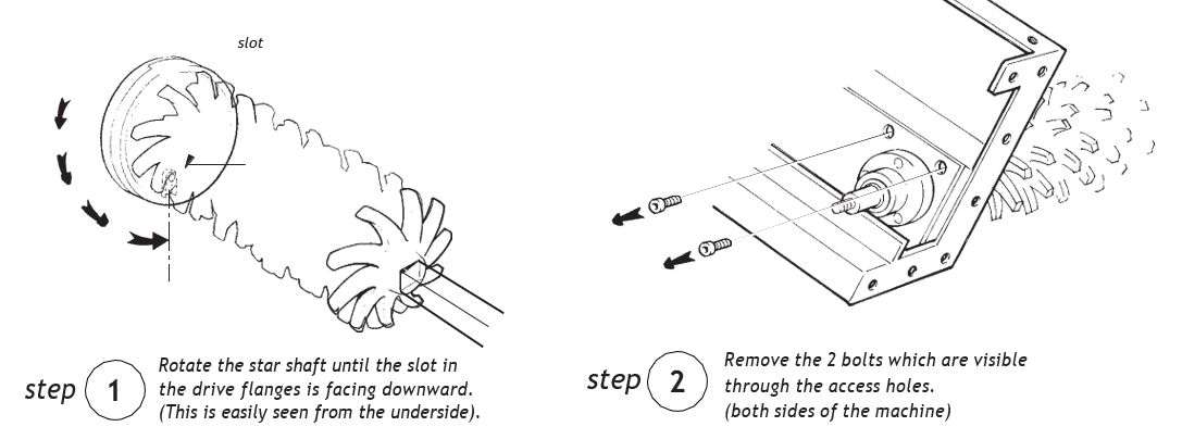
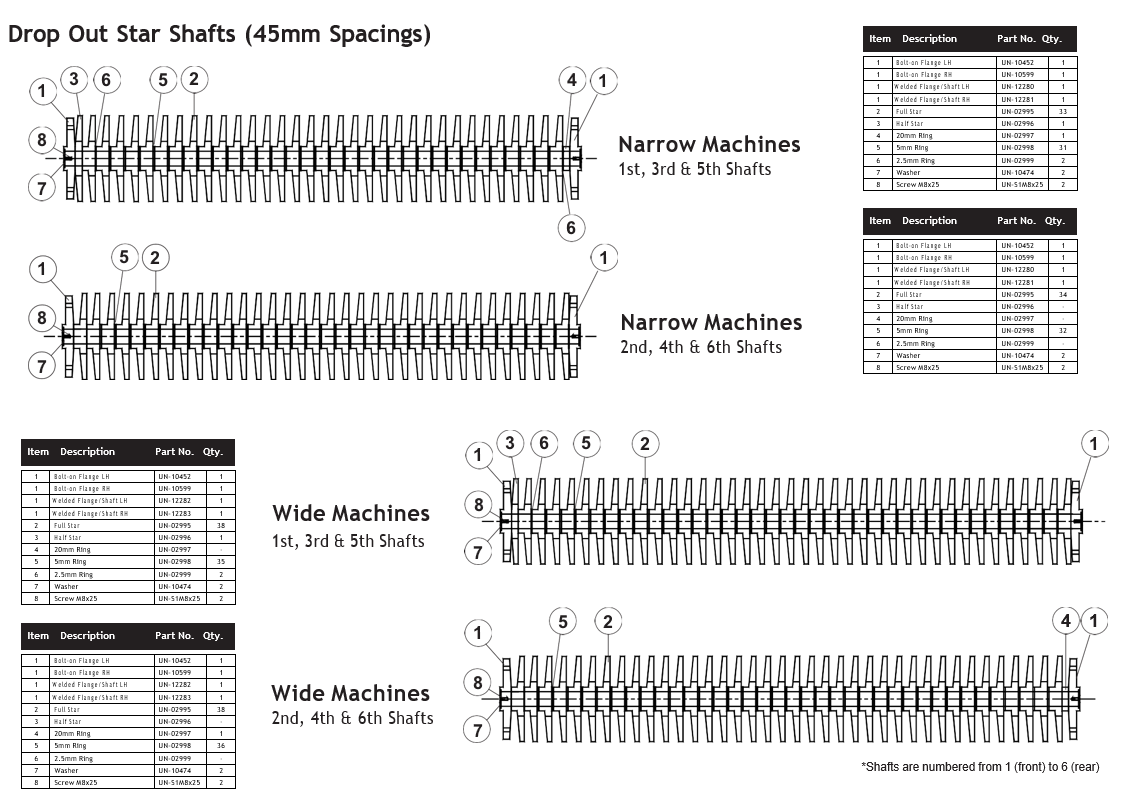
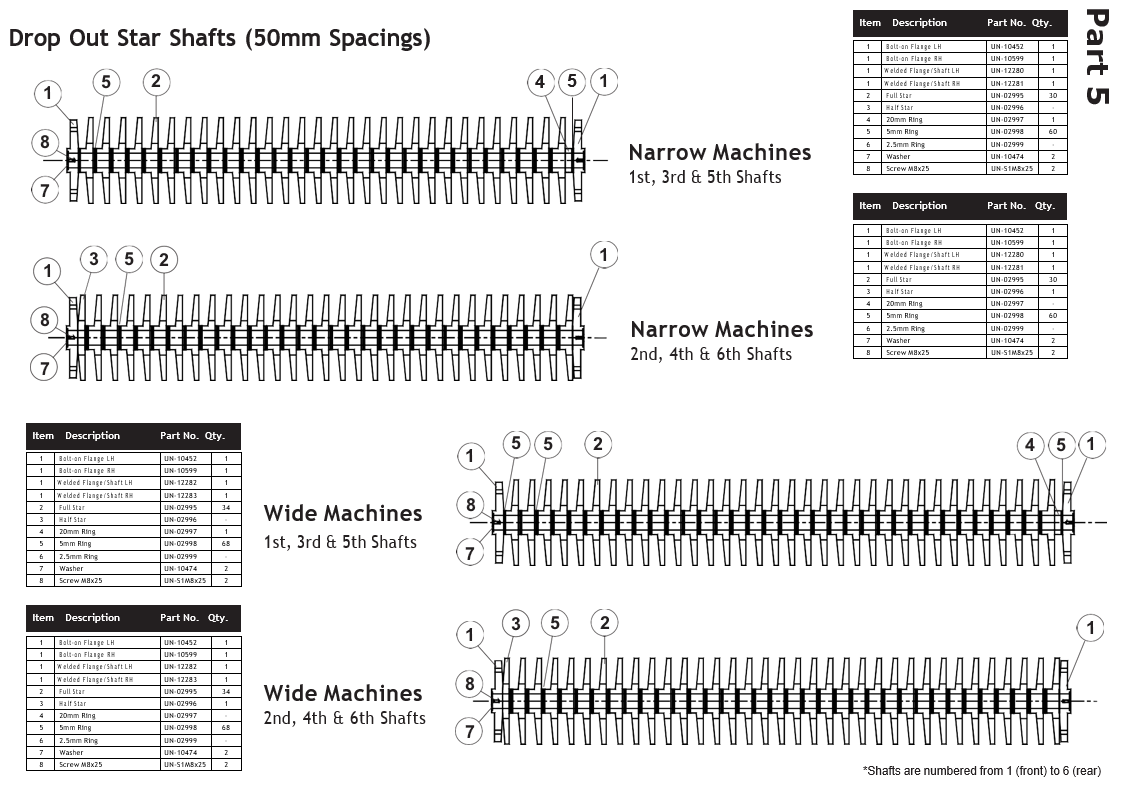
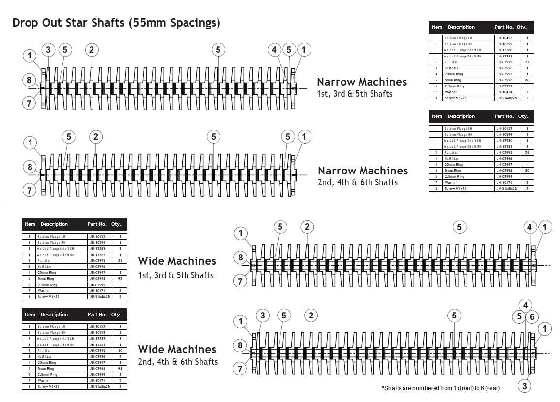
Star Shaft Removal and Replacement
The high output Star unit consists of 6 rows of polyurethane stars mounted on heavy duty demountable steel shafts.
The shafts are designed with 2 piece interlocking drive flanges at each end which allow them to be detached and lowered out of the unit quickly and easily without the need to remove drive belts and pulleys.
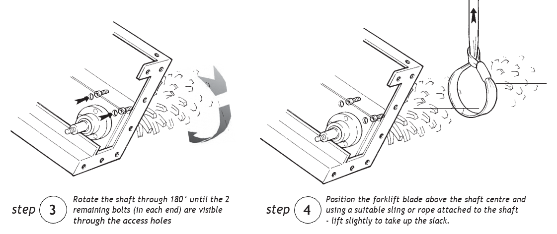
Take care when removing shafts - Heavy lifting may be involved. Use a forklift with suitable sling to attach the shaft when lowering.
Keep hands and feet clear when lowering shafts.
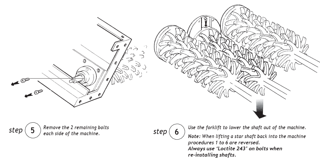
Shafts can be removed by following steps 1 to 6 below.
Note: When re-installing a star shaft position the shaft on the ground and rotate until the small groove in the flange face is in the upward facing position.
This ensures correct seating with the locating pin in the chassis half of the flange.
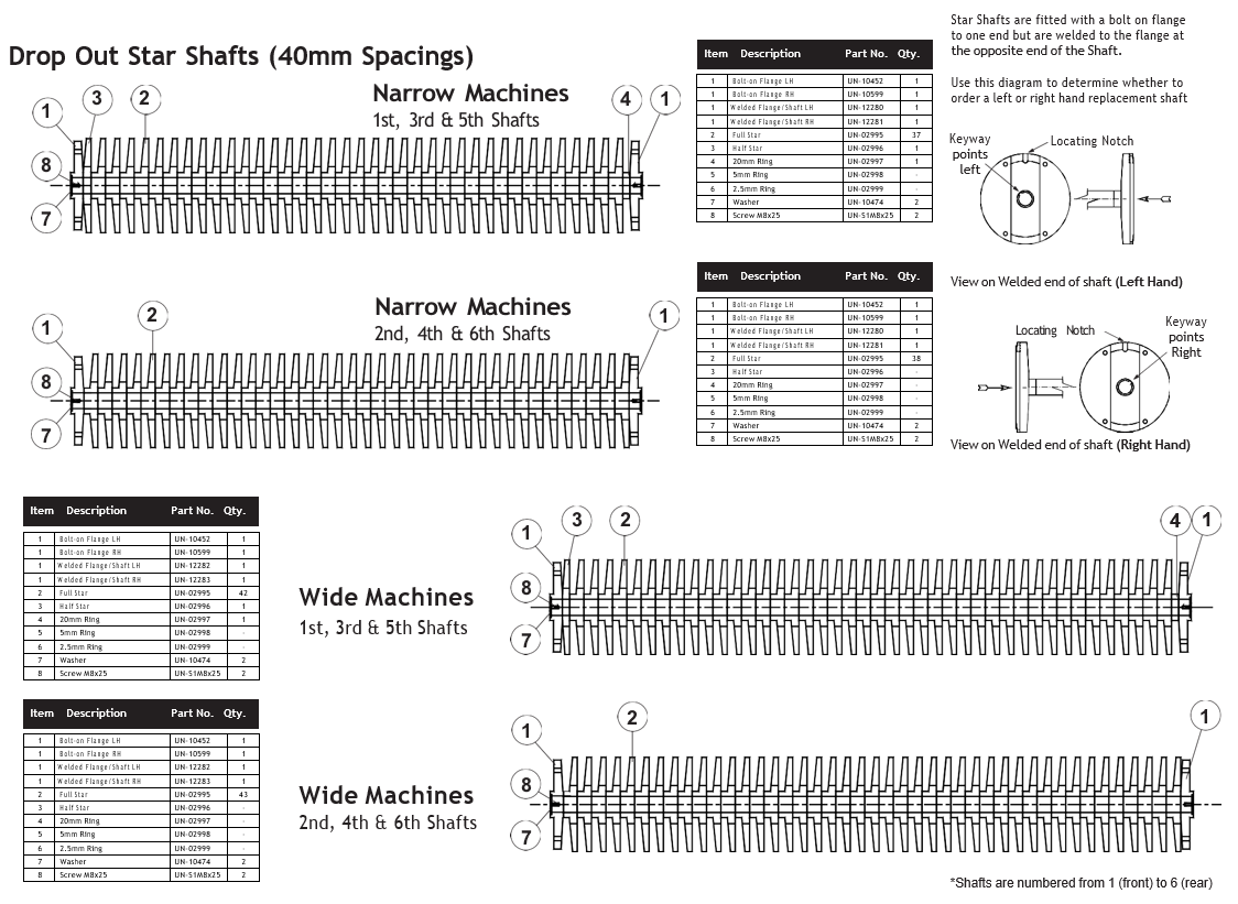
For details of alternative star pitches and shaft assembly drawings see below.
Machines Before 2018
Rear Star Unit
The rear star unit consists of 3 driven star shafts designed to convey large stones into the stone collection hopper. Spacers positioned between each star allow small or medium sized stones to fall through onto the cross conveyor for removal into the row bottoms.
Each star shaft can be easily removed to allow worn stars or spacers to be replaced if necessary.
To replace stars / spacers:-
- Detach the carbine hooks holding the scrubber web extension in position, Fig 5.10.1 and lift web clear of the shafts.
- Remove deflector plates bolted either side of the machine, Fig 5.11.1 to allow access to the shaft end flanges.
- Remove the 3 bolts in each end flange, Fig 5.11.2 splitting the flanges into two parts. Remove the smaller part to allow the star shaft to be lifted out of the machine.
- Remove the socket head countersunk screw from the centre of the end flange to allow the stars and spacers to be removed from the shaft.
- Reverse these procedures when re-fitting the shaft.
Note: Shaft bearing housings each have a grease nipple for lubrication. These require 1 pump of grease every 100 working hours.
The clutch also has a grease nipple which requires 1 pump of grease every 200 hours, - see Lubrication schedule.